Posts

Blog #6

Image
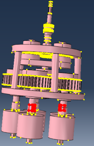
      Since the last blog, we've been working to perform a FEA on the design to determine weak points and to ensure that the design would not buckle under stresses. However, the FEA was difficult to perform due to complications with the geometries of the design that prevented it from meshing properly. Figure 1. Areas highlighted showing areas that cause the meshing to fail      Figure 1 shows the regions that failed to mesh properly. The complex geometries of the gears and internal components connected to the shafts made it difficult to perform a FEA. Using the entire design also meant a large amount of elements would be analyzed and require too much time to complete the analysis. After meeting with Dr. Agrawal, we determined the main weak point of the design would be the rotary component that connects and transfers torque from the planetary assembly to the delivery assembly, with the potential cause of failure ...

Blog #5 : Progress since Winter Break

Image
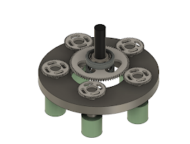
     Over the break, not much work was done for the project. The design was pretty much finalized last semester and was left alone  over the break . A design flaw was noticed by the team once the semester started and it was that the top and bottom plates were not connected to the device, resulting in them just floating in space. The CAD design is finalized, but 3D printing the sockets and top plate of the device still remains to be completed. Figure 1 (Left Image) and Figure 2 (Right Image). Updated design of the device      Figure 1 shows the finalized design from the Fall semester, and Figure 2 shows the updated design after. What we decided was to weld them together with rods. This was in place of having a sleeve cover the gears. We decided against a sleeve because it would make the device heavier, and the added cost of the metal for the sleeve is too much for the team at the moment.     In the next coming weeks, we plan on doing more...

Blog #4

Image
Currently, we have worked on the analysis for the project. We had some initial looks to make sure the lug nuts are able to turn and we went based on that. Now we are looking into the exact predicted torque and the issues of under and over tightening are becoming an issue. Another obstacle we are tackling is the cost. We have overlooked some of the costs and are trying to change the design in a way that would allow us to save money and still be functional.  As of now, our design has a central driver gear and 5 driven gears. In this layout, the torque from the drill is split evenly into each gear and then doubled from the gear ratio of 2. This in theory is ideal, but there is still the possibility of a gear initiating before the rest and this could lead to over tightening. To combat this we have a torque limiter on the ends of the sockets. This would allow us to make sure that each lug nut is not being over tightened and it will prohibit any gear from not being tightened properly. ...

Blog #3 : Current Progress Update

Image
   Our team has changed projects a few times, but we're finally settled and approved for our latest: a multi-spindle that you can use for removing and installing lug nuts! Since our progress report presentation, we've finalized the vehicle we're going to model the deign off. This is the most important step, primarily because of how many unique factors the vehicle demands. Specific spindle arrangements, differing depths, manufacturer keys, housing size and geometry, and simple availability have enormous impacts on the specifications the multi-spindle would have. From this, we've created a CAD of initial designs that we want to iterate upon as we explore options regarding the torque issue.  One design was a single-driver gear and the other was a drive shaft with multiple driver gears. Each design is still in its preliminary phases, but we are continuously working on refining them. Currently, we are looking into what gears we can purchase since the machinist cannot manufac...

Blog Post #2: Update on problem Statement and Goals

Image
In the last blog post, we proposed to design and develop an aerial defense system that concentrates sunlight to be able to melt through materials used for aircraft. After developing the project plan, we realized that this design was too ambitious and wouldn’t fit into the timeline for completion of Capstone. Some reasons include feasibility, budget, and time to complete the design. There would need to be multiple research conducted to ensure a working device performing aerial defense since there currently isn’t any development into this topic. Researching along with constructing the device would take more time than Capstone offers, as well as money used for research, experimentation, software, and design construction. This project has proven to require much more research than anticipated. After consulting Professor Chen, we have decided that this project is not a viable project for capstone. In order to pursue this project, funding and time are needed and we do not have this at this mo...

Initial Look

Image
Government aerial defense is indispensable in protecting a nation's security and airspace from potential threats, such as hostile aircraft and missiles, serving as a deterrent against airborne attacks and escalations in conflicts. These systems play a critical role in safeguarding vital infrastructure, ensuring the uninterrupted flow of essential services, and maintaining border security. Additionally, they enable swift responses to emergencies, including natural disasters and terrorist incidents, contributing to the overall safety, sovereignty, and well-being of the nation and its citizens. Recent developments have highlighted the significance of these defenses, with the United States engaged in an arms race as countries like China introduce advanced technologies, such as hypersonic missiles, posing new challenges and necessitating ongoing vigilance. (Howard & Mailonline, 2022) Team 23 proposes to develop a concept that aids with aerial defense during the daytime by using the ...