Blog #5 : Progress since Winter Break
Over the break, not much work was done for the project. The design was pretty much finalized last semester and was left alone over the break. A design flaw was noticed by the team once the semester started and it was that the top and bottom plates were not connected to the device, resulting in them just floating in space. The CAD design is finalized, but 3D printing the sockets and top plate of the device still remains to be completed.


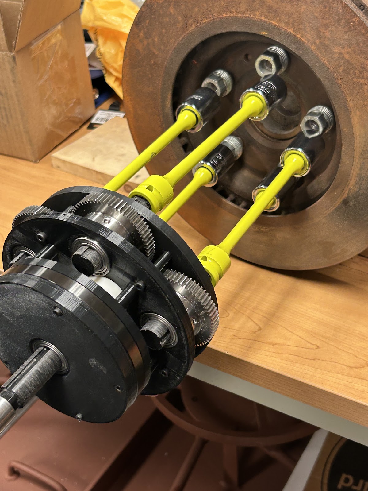
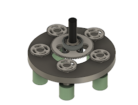
Figure 1 (Left Image) and Figure 2 (Right Image). Updated design of the device
Figure 1 shows the finalized design from the Fall semester, and Figure 2 shows the updated design after. What we decided was to weld them together with rods. This was in place of having a sleeve cover the gears. We decided against a sleeve because it would make the device heavier, and the added cost of the metal for the sleeve is too much for the team at the moment.
In the next coming weeks, we plan on doing more simulations on the CAD, this came after talking with our advisor and him requesting for more simulations to be done to ensure the device does not buckle under stress. Also, some 3D printing will be done to ensure alignment with the target vehicle. The team will print the top plate and the sockets in their correct place to ensure the proper spacing was met. For the simulations, we were advised to use Comsol instead of SolidWorks. Comsol would allow us to do more and would be more accurate. A slight issue with this is the team is unaware how to get access to Comsol, so the professor was emailed to see if it's possible to use Comsol for the simulations.
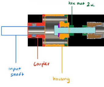
Figure 3. Torque Limiter
Some problems we see happening are issues with the torque limiters, shown in Figure 3, that we planned to use. After more looking, we could not find a cheaper alternative to them and their cost increases the total budget. Development on the torque limiter is also more complicated than it appears due to multiple components needed to build one, which also requires research to select and design the parts for the desired torque threshold. One possibility is to omit them which would save the team hundreds of dollars but slightly change the scope of the project since cross threading can occur.
Another problem we could see is the alignment. If we did not take proper time to correctly align the CAD, then we would need new gears and more time to ensure they will fit and not buckle. For this issue, we can ensure the buckling wont happen since the gear material should not change since the gear manufacture would not change as well. Also, the team is confident that the alignment is correct, but that still needs to be validated hence the printing will happen.
One last issue is the use of software to create simulations of the CAD. Comsol might not be available at the moment, and creating simulations using SolidWorks might have more restrictions on applicability. To attempt creating simulations, one solution is to find and use other software available to us.

Comments
Post a Comment