Blog #6
Since the last blog, we've been working to perform a FEA on the design to determine weak points and to ensure that the design would not buckle under stresses. However, the FEA was difficult to perform due to complications with the geometries of the design that prevented it from meshing properly.
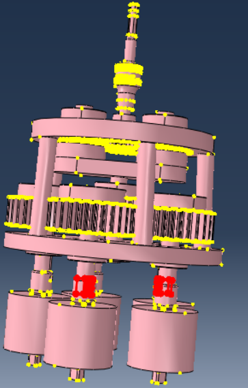
Figure 1 shows the regions that failed to mesh properly. The complex geometries of the gears and internal components connected to the shafts made it difficult to perform a FEA. Using the entire design also meant a large amount of elements would be analyzed and require too much time to complete the analysis. After meeting with Dr. Agrawal, we determined the main weak point of the design would be the rotary component that connects and transfers torque from the planetary assembly to the delivery assembly, with the potential cause of failure for the connection being the shear stresses acting on the component.
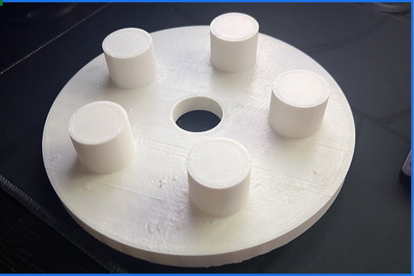
Figure 2 shows the top plate 3D printed along with cylinders that represent the position of the sockets. Cylinders were simpler to 3D print to minimize time and resources used. With the 3D printing complete, we then tested the alignment.

Figure 3 shows the 3D printed component used to determine possible misalignment with the sockets. The cylinders seem to align with the lug nuts closely, but it wasn't perfect. Since the cylinders were printed much larger than needed, it was hard to determine the exact alignment.
We hope to order the components in the next few weeks. Since we are getting nearly all of our metal from McMaster Carr, we should receive the order within a week. This would allow us to create the gear assemblies and ensure that they are functioning appropriately. Once the components arrive, we hope to get the planetary gear assembly built, putting us closer to finish assembling the device together. We are also going to try printing the socket heads of size 3/8 inches to better determine if sockets align with the lug nuts.
We are also considering to continue the FEA, only focusing on the component that connects to the two assemblies. However, the FEA is much less a priority after being provided with clarity on the potential failure of the device, as well as the stresses that can act on the component.
Some obstacles are the led time to get the top and bottom plates machined. Since we are getting our material soon, we would be in a line at the machinist to get the work done, but since minimal work is needed we would expect the parts to be ready fairly soon given the circumstances.
Another possible problem is with the top plate. When we tested for the alignment, we see that not all of the bolt heads sit in the center. If the top plate shows problems with alignment, we would need to redesign it to ensure the sockets connect to the lug nuts, which can cause delays in building the device. To combat the time lost, we plan to acquire and assemble other components to ensure the planetary gear assembly is completed while the delivery gear assembly is still in progress.
The last problem we foresee is the FEA still being difficult to perform. If we are still struggling with the FEA, we will need to move on to focus on assembling the device since building it will require more focus. We will need to create possible solutions to reinforce the component that connects the two assemblies while also falling within the geometric constraint of fitting within the middle bore diameter of the gear rotating the other delivery gears. Some possible solutions for this is attaching a thicker tube to the component or using stronger materials to fabricate it.
Comments
Post a Comment