Blog #4
Currently, we have worked on the analysis for the project. We had some initial looks to make sure the lug nuts are able to turn and we went based on that. Now we are looking into the exact predicted torque and the issues of under and over tightening are becoming an issue. Another obstacle we are tackling is the cost. We have overlooked some of the costs and are trying to change the design in a way that would allow us to save money and still be functional.

At some point, the nut will be tightened and the resistance to the input torque dramatically increases around the assembly torque Ta, until failure, and the resistance torque drops. This occurs at failure torque Tf

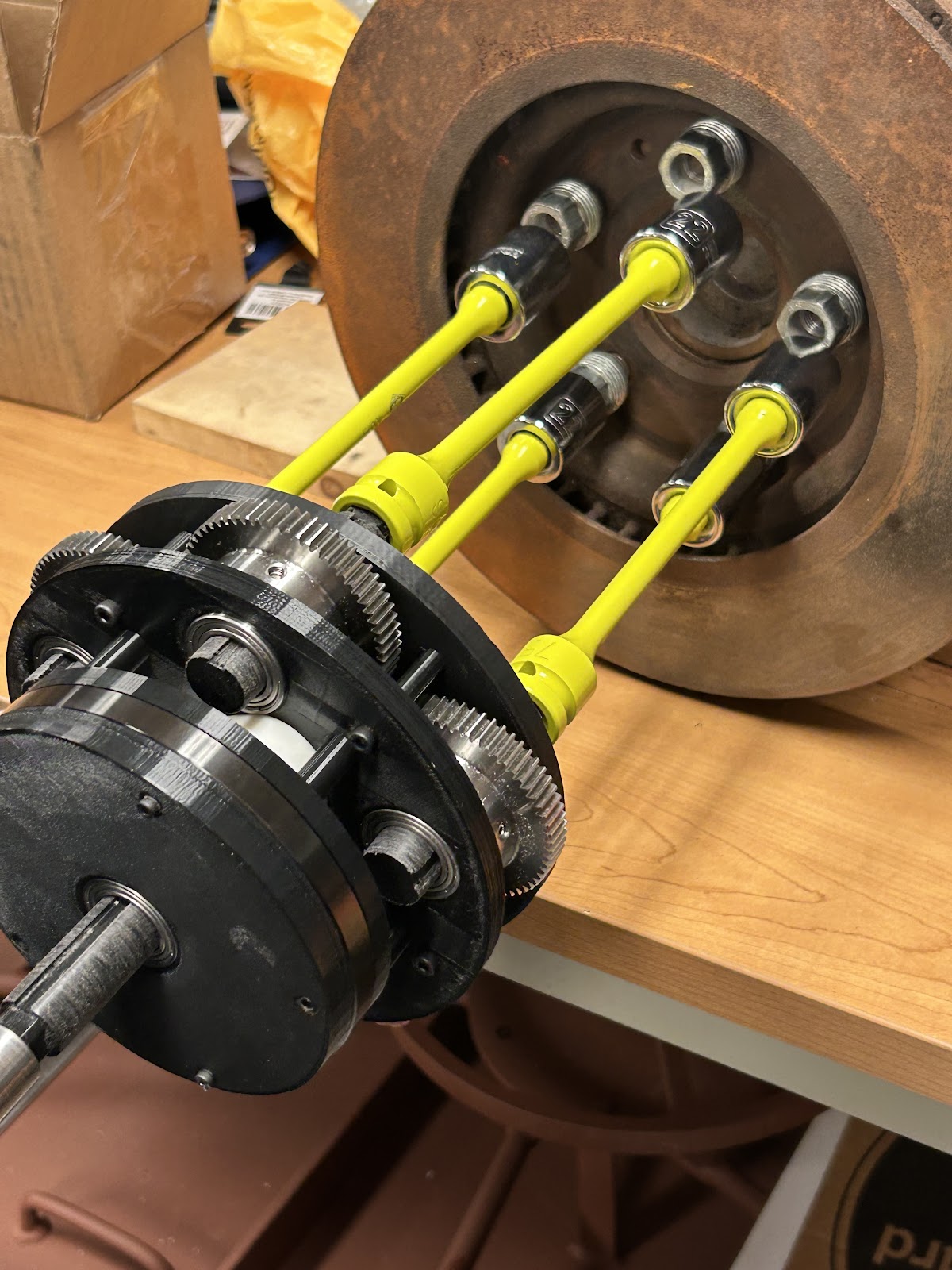
The objective is to reduce the unequal distribution of torque. We observe that one socket, which we have dubbed the “priority socket,” will be overtightened, and the others under. We believe that by installing friction torque limiters, the torque may be more evenly distributed. To determine how torque is spread, we will use a mechanical circuit to describe the system behavior.
The rules of such are:
Torque is defined as current (I)
Rotational Speed is defined as voltage (V)
Gear Ratios are captured with a transformer
Inertia is captured with capacitance (C)
Friction is captured with resistance (R)
To represent the torque limiter, we’re going to use a circuit breaker

The first difficulty associated here is the parallelity; determining what percentage of torque is actually delivered to each gear. To cheat, we instead focus only on the boundary condition:
For some optimal assembly torque Ta, we can set the friction torque limiter to this value or close to it. At this limit, the circuit breaker is open, and most of the current- (torque) -is reallocated to the remainder of the gear assembly. Some still remains in overcoming friction and the rotation of the torque limiter with low resistance.
In theory, by setting these limiters to the locking torque, the spindle will deliver a near equal amount of torque among all the lug nuts.
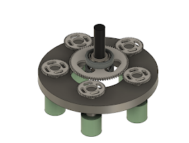
The second difficulty here is that torque limiters do not work well with impact drivers, which means we’re limited to handwork and drill drivers, which is a significant loss of torque. At this point it is now necessary to find a way to increase the torque output; To save space, and money by focusing on commercially available parts, we’ve decided to use two planetary gear assemblies in series.
We can maximize the gear ratio and thus torque output by holding the ring gear, lowering the number of sun teeth, and increasing the number of ring teeth.

Manufacture specifications include information about the threading, locking, and failure torque for the lug nut. Allowing us to set the limit L to the given Ta.

The third difficulty is cost. The torque limits we’ve seen are extremely expensive, and may be the primary factor in the disuse of multi spindles.
Comments
Post a Comment