Blog 7: Updates on Assembling the Lug Nut Remover
Since the last blog, we have fixed the issue with the plate's alignment with the desired wheel. Our desired dimensions are a 5x120 mm lug nut pattern, but the actual dimensions of the wheel were 5x114.3 mm. We decided to make a testing stand to allow us to showcase the device on campus and to avoid redesigning the delivery assembly, due to difficulties with ensuring gears mesh properly within actual dimensions.
.
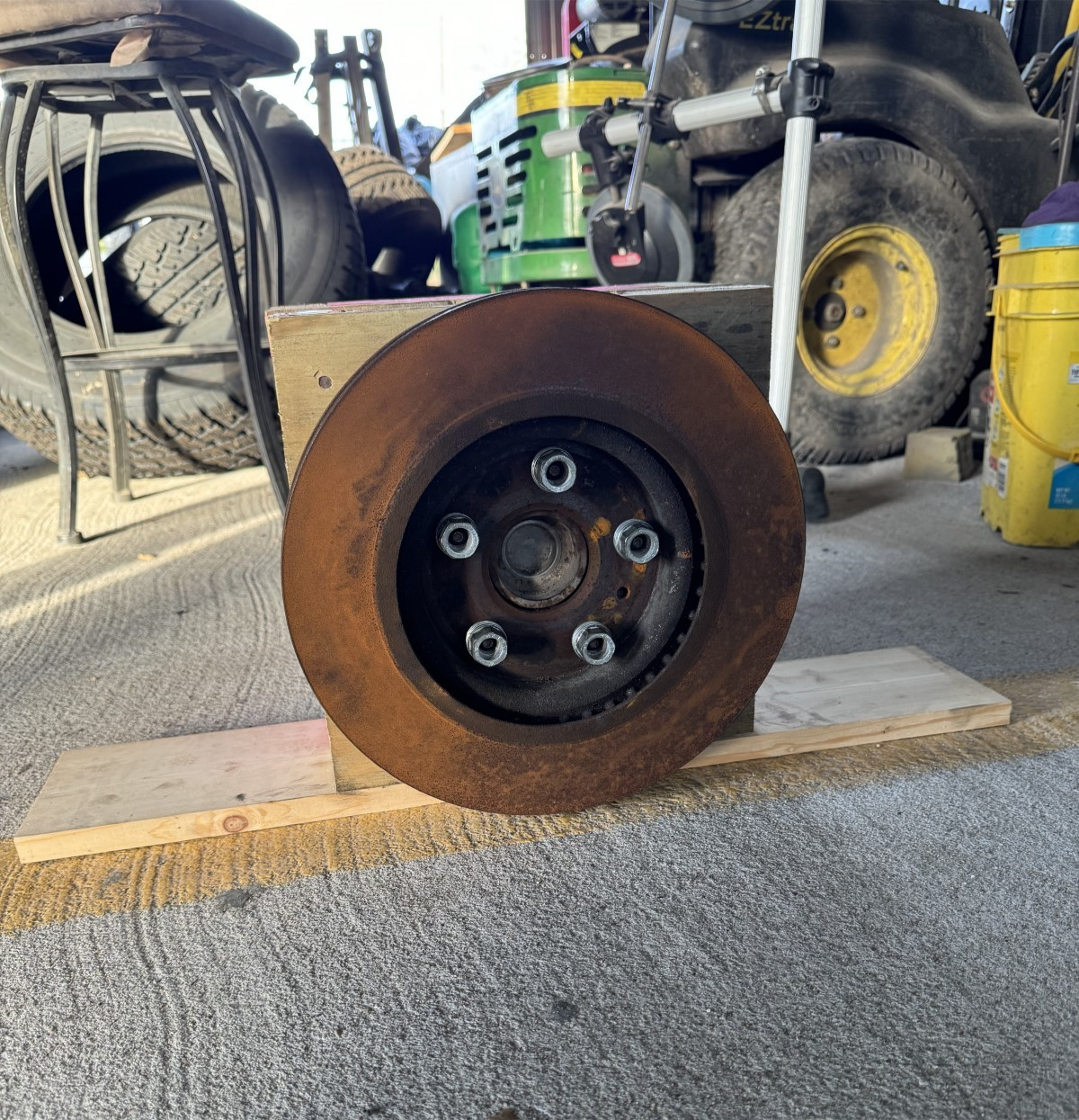
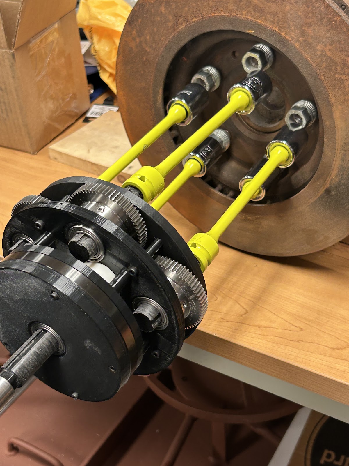
Figure 1. Testing Stand
Figure 1 shows the finalized testing stand with desired dimensions that match with the positioning of the device's sockets. The stand uses wooden slabs, where the hub assembly sits between them. Holes were drilled to fit the lug nuts through one of the wooden slabs. To ensure that the lug nuts sit in place with minimum movement, washers were used to fill the gaps created by the lug nuts and holes. This took a couple of tries due to some washers bending while attempting to fit them in the holes. Finally, a foundation was added to prevent the stand from tipping over, allowing it to be operated on without it requiring two people to hold the stand in place.
Although it's too late in our schedule to update any design changes, we decided to make last minute changes before ordering the parts to assemble the device. We have finally finished updating the device, clearing the first milestone for any updates.
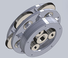
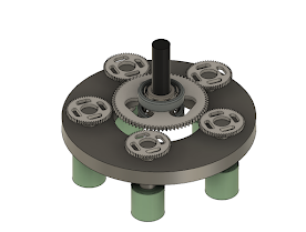
Figure 2. Design of gear assemblies and carrier shaft that connects to them
Figure 2 shows the planetary and delivery gear assemblies, as well as the carrier stock that will transmit the amplified torque to the delivery assembly. We originally had 2 planetary gears revolving around the middle gear (sun gear). However, we were recommended to use 3 planetary gears instead of 2 to ensure that the load distribution among the gears is stable, further avoiding unforeseen issues with transmission of torque. With the addition of 1 planetary gear, the carrier stock was redesigned to be able to connect to all 3 planetary gears. The issue with the carrier stock and shafts potentially failing was also approached by increasing the diameter to withstand higher shear stresses. We also decided to change the gears to being keyed.
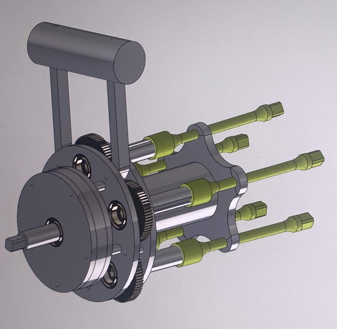
Figure 3. Finalized design concept of the entire device
Figure 3 shows the final design concept of the lug nut remover. We added casings to cover the gear assemblies to ensure the gears are properly covered and secured in place. A handle was also created to allow us to hold the device while operating it.
Notice the torque limiters that connect to the delivery assembly. We we were able to find affordable torque limiters, which allows us to address the issues with overtightening. The torque limiters are long, and we can't shorten them since the base of the torque limiter would have to be thicker if the torque limiters become shorter. We added another plate that holds the torque limiters steady, which is connected to the delivery assembly's plate by a hollow tube. The plate that touches the torque limiters is attached by clips to hold them in place.
After finishing the design updates, we are now focused on completing the second milestone of building the device. We have already purchased all parts and gears required to build the lug nut remover. What remains is to finish machining parts needed to assemble the device. We are currently planning to reduce the stock with a lathe, key it with a mill, and make the bit a square.
We are looking into 3D printing the casings that cover the gears to save money. The main load distributions are experienced by the gears and shafts, so we assume that there won't be any loads experienced by the device's casings. This allows us to use weaker material that doesn't need to withstand high amounts of stress. Once the casings are 3D printed, we can attach them to the device.
We're currently waiting for other parts to finish being delivered and machined. Once all of the manufacturing is finished, we will begin assembling the device by the end of the week.
Some challenges we foresee is the time required to machine. We are also trying to figure out how to perform heat treatment and are considering using the materials science lab at our university, if available. Since this could take more time than anticipated, we might not be able to finish building the device in time. We will have to notify our advisors to discuss our schedule for the device. We also hope that 3D printing the casings will save time on machining parts. The final design changes were intended to allow us to assemble the device quickly, giving us up to 2 days to finish assembling the entire device. The team is far behind schedule, but we are hoping that the short time window estimated to start assembling the device will allow us to catch up to the third milestone of validation.
The last challenge will be the possibility that the gears can break while the device is operating. The issue with the lug nut overtightening is prevented with torque limiters, but the torque transmitted by the drill driver can still affect the gears and shafts. We will use a drill driver with enough torque to be able to tighten and loosen the lug nuts but not high enough to cause the gears to fail.

Comments
Post a Comment