Blog #8 - Assembling the Lug Nut Remover and Current Validation Updates
Since our last update, we have been working to assemble the multi spindle lug nut remover. All the parts have arrived, and we managed to 3D print the casings that cover the gear assemblies along with the handle to hold our device. The main issue was having the steel shafts and carrier stock machined in time to incorporate it into our device for the demo. Since we anticipated that the shafts would take longer to machine, we decided to 3D print the shafts and carrier stock using PLA material. With the shafts and stock 3D printed, we were able to assemble the entire device fairly quick. The process involved using heat to melt some of the PLA to allow parts of the handle, the shafts, and the contact bearings to fit into the the casings. We also drilled holes into the internal ring gear to place the gear and casing together with screws.
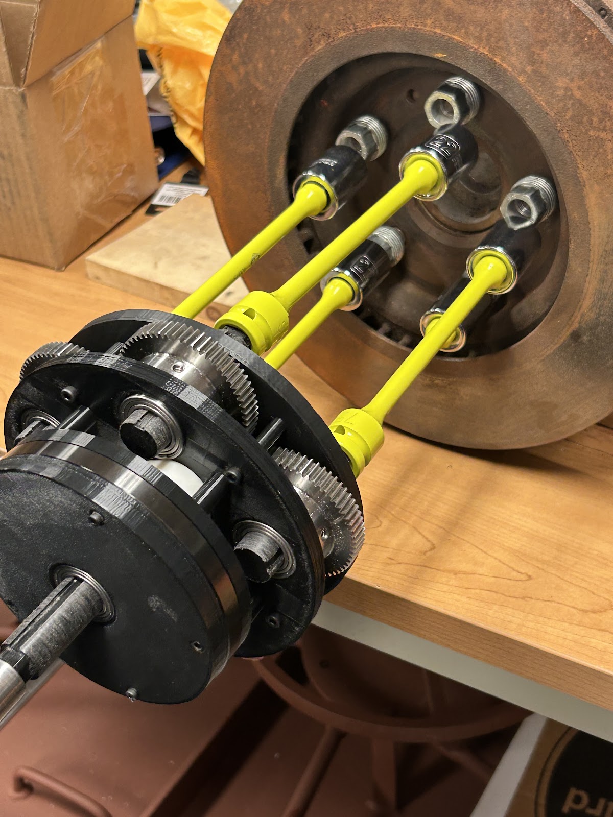
Figure 1. Fully assembled device
Figure 1 shows the fully assembled multi spindle tool with torque limiters attached to the tested hub assembly. We managed to create a working prototype of our design, officially completing the second milestone of assembling the device together.
After the demo, we've been making changes to our device. This started with needing the change the shafts that were used. These shafts were 3D printed with a low infill since they are to get replaced with metal shafts. Here arose the issue. Since the demo, we were able to get an accurate measurement of the shafts needed to give to our manufacture. Since then we have not been able to contact them. In fear of not having the metal shafts in time, we decided to reprint the shafts with a higher infill.
We understand that these new shafts are not capable of withstanding the load we intended. After talking to Dr. Agrawal, we decided to run tests with a lower RPM from the drill to see a correlation. From this, we measured the RPM that we ran the drill at roughly 60 RPM. The table below shows the RPM of the device.
Table 1. RPM measurements
The table shows us that we measured a lower RPM than expected. This value was calculated by multiplying the drill's rpm by the inverse of the overall gear ratio that was calculated to be 1.23. The difference in the value can be attributed to friction between the gears and the PLA. This was expected, so we plan on rerunning the test after applying a silicone lubricant throughout the device.
Another test we ran was measuring the torque of the shafts with and without load. This was done by having a torque meter attached to one of the shafts and running the device. The with load test means that the other shafts had resistance and without load means that the shafts were free to spin without being connected to anything. The table below shows the readings from that.
Table 2. Torque readings of each socket with load and without load
The difference in the torque is expected because since the gears have more of a resistance with load than without load. These values are lower than what we had planned for, again because we did not run at the drill's full power due to us being cautious not wanting to break the 3D printed shafts.
The team chose to see how the 3D printed parts can hold up to the tests. We were able to print the base plates and other components since they do not experience load. We do however want to see if there is some wear and tear. A simple way of testing for this was given by Dr. Agrawal. We took the device apart and visually inspected the components, shown below in figure 1. This process is to be repeated at the end of our validation to see how the PLA components had held up.
 |
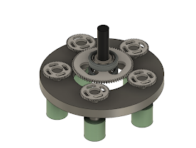
Figure 2. Planetary System before use of the device |
We plan to hopefully get the metal shafts. We will also try reducing the friction between the shafts and the bearings since this can cause the torque distribution and RPM for each gear to be unsteady. We also had issues where the driven gears weren't rotating due to the driver shaft not being properly attached to the carrier stock, so we recommend adding a set screw to secure them in place. Finally, we would also move the handle backwards to prevent it from hitting the gears that would contribute to friction contact and wear and tear.
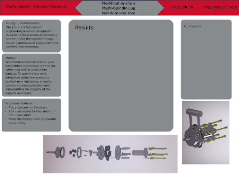
We are currently working to finalize our validation results since we mainly have results for the device's performance and not for its condition. Below is a current rough draft of our poster. We will refine the visual quality of it, as well as filling in the empty sections once the validation is done.

Comments
Post a Comment